Testing an Outboard Rectifier / Regulator
A rectifier or voltage regulator is a common failure point when an outboard battery will not charge. This guide walks through basic diode-test checks using a multimeter.
Complete guide: Outboard Ignition Testing Guide
Related ignition tests: Switch Box Testing | Power Pack Test | Stator Testing Guide | Ignition coil test | Trigger Timer Base Testing
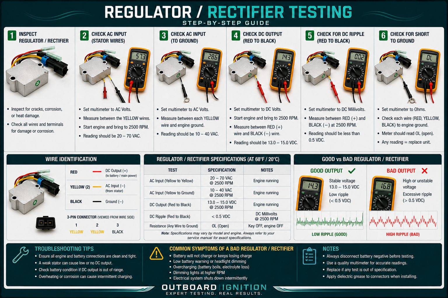
Testing an outboard motor rectifier/regulator involves using a multimeter in diode test mode to confirm that current flows in only one direction through the internal diodes. A good rectifier commonly shows about 0.5 to 0.6 volts in the forward direction and OL or open circuit in the reverse direction. A faulty rectifier may cause a battery that will not charge, erratic charging voltage, or an overheated rectifier/regulator unit.
Voltage Regulator Rectifier Testing Overview
Preparation and Initial Checks
Testing Procedure: Diode Test Method
- Set the multimeter to diode test mode: Use the diode symbol setting on the meter.
- Forward bias test: Connect the black negative meter lead to the rectifier’s red DC positive wire. Touch the red positive meter lead to each yellow AC wire one at a time. A typical reading is about 0.5 to 0.6 volts.
- Reverse bias test: Reverse the leads. Put the red meter lead on the red DC positive wire and the black meter lead on each yellow AC wire. The meter should show OL or open circuit.
- Ground side test: Connect the red meter lead to the black ground wire or metal case. Touch the black meter lead to each yellow AC wire. A typical reading is about 0.5 to 0.6 volts.
- Reverse the ground test: Put the black meter lead on ground and the red meter lead on each yellow AC wire. The meter should show OL or open circuit.
Interpreting Results
Other Potential Issues
If the rectifier/regulator passes diode testing but the battery still does not charge, the stator may be the problem. Test stator output by measuring AC voltage from the stator wires with the engine running. Many systems may show roughly 20 to 40 VAC depending on design and RPM. Also inspect connectors for melted plastic, especially where the regulator connects to the main harness.
Browse Related Charging Parts
Use these categories after confirming your engine brand, horsepower, year, serial number, and original part number.
Before You Order
For best fitment help, have your engine brand, horsepower, model year, serial number if available, old part number, and charging voltage readings ready.
(918) 457-4099If the rectifier tests good, check stator AC output and wiring condition before replacing parts.