Testing an Outboard Trigger / Timer Base
The trigger or timer base tells the ignition system when to fire. Bad readings, inconsistent coils, shorts to ground, or mechanical binding under the flywheel can cause ignition timing and spark problems.
Complete guide: Outboard Ignition Testing Guide
Explore related ignition testing guides: Ignition Coil Testing | Switch Box Diagnostics | Power Pack Troubleshooting | Regulator And Rectifier Check | Stator Output Test
Testing an outboard motor trigger or timer base usually involves measuring resistance between wire pairs with a multimeter. Common checks include measuring from the white wire to colored trigger wires such as blue, purple, or green, often looking for readings in the 15 to 50 ohm range. Some white to white/black checks may read around 400 to 500 ohms. Inconsistent readings, a zero reading, OL where a number is expected, or any short to ground can indicate a faulty trigger or timer base. A DVA adapter provides more accurate voltage testing while cranking.
Overview For Testing Trigger/ Timerbase
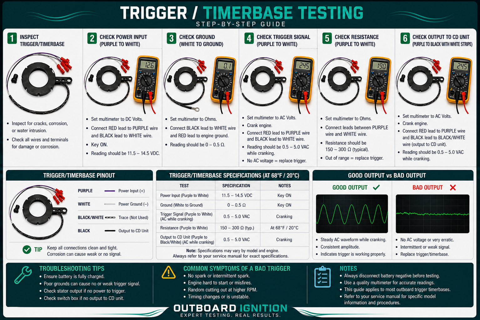
How to Test the Trigger / Timer Base
- Disconnect and identify: Locate the trigger wire connector near the stator area and disconnect it from the switch box or power pack.
- Set the meter to ohms: Use the lowest ohms scale that gives a stable reading.
- Test common trigger leads: Measure between the white wire and the colored wires, commonly blue, purple, and green.
- Compare expected values: Readings commonly fall in the 15 to 50 ohm range, but always verify the exact specification for the engine.
- Check white to white/black: On some systems, this circuit may read around 400 to 500 ohms.
- Check for shorts to ground: Place one probe on each trigger wire and the other on engine ground. The meter should show infinite resistance or OL.
- Compare all readings: The trigger coils should be relatively consistent. A 0 reading, OL where resistance is expected, or a large mismatch usually indicates a problem.
- DVA test when possible: Use a DVA adapter to check trigger voltage output while cranking for more accurate diagnosis.
Interpreting Results
Important Notes
Browse Related Ignition Parts
Use these categories after confirming your engine brand, horsepower, year, serial number, and original part number.
Before You Order
For best fitment help, have your engine brand, horsepower, model year, serial number if available, old part number, and resistance or DVA readings ready.
(918) 457-4099If the timer base does not rotate freely or the readings are inconsistent across coils, call before replacing related ignition parts.